Jan 07, 2023
A pneumatic cylinder converts the energy of compressed air into controlled mechanical motion. In most industrial machines, that motion is linear: a piston moves inside the cylinder barrel, and the piston rod transfers the movement and force to a mechanism outside the cylinder.
The principle is simple enough to explain in a few sentences, but understanding how a cylinder actually works requires more than saying that “air pushes the piston.” The directional valve has to route air to the correct chamber, the opposite chamber has to exhaust, the piston must remain sealed while moving, and the cylinder must be mounted so its force can be transferred into the machine without creating unnecessary side load.
This guide follows that complete working cycle and explains how pressure, bore, stroke, airflow, mounting, and different cylinder structures affect the motion you see on the machine.
Compressed air stores pressure energy. A pneumatic cylinder converts part of that pressure energy into mechanical force and motion at the piston and piston rod.
Inside a conventional rod-type cylinder, the piston divides the barrel into two chambers. When compressed air is supplied to one chamber, the pressure acting over the piston area creates force. If that force is high enough to overcome the opposing load and internal resistance, the piston moves. The piston rod then transfers that movement to the machine.
This distinction is useful: pressure does not directly “create speed.” Pressure acting on effective piston area determines the theoretical force available, while the rate at which air can enter and leave the chambers has a major influence on how quickly the cylinder can move.
Double-acting cylinders are common in industrial automation because compressed air controls motion in both directions. A typical cycle can be understood in four steps.
A directional control valve connects the compressed-air supply to one cylinder port. The chamber on that side begins to pressurize.
As pressure builds, it acts over the effective piston area. Once the available force exceeds the opposing load and friction, the piston starts to move. The piston rod carries that linear motion outside the cylinder.
The piston cannot move freely if the air on the opposite side has nowhere to go. The directional valve therefore connects the opposite chamber to exhaust. Valve size, tubing, fittings, silencers and flow controls can all influence how easily the chamber fills and exhausts.
To reverse the motion, the valve changes state. Compressed air is sent to the opposite chamber, while the previously pressurized chamber is connected to exhaust. The piston and rod then travel in the other direction.
The stroke is the usable travel distance of the piston from one end position to the other. If a cylinder has a 200 mm stroke, the piston and rod can travel approximately 200 mm between their designed end positions. Stroke determines how far the mechanism can move; it does not by itself determine how much force the cylinder can produce.
For many standard machines, selecting stroke is mainly a matter of matching the required travel. Longer-stroke applications need more attention because the rod extends farther from its support. Depending on the load and mounting arrangement, rod stability, deflection, guidance, alignment and buckling risk can become more important as stroke increases.
In custom long-stroke cylinder projects, increasing the barrel and rod length is therefore only part of the design. Fescolo engineers also check how the load is guided, the direction of force, mounting arrangement, available installation space and operating speed before finalizing the cylinder configuration.
These four parameters are often discussed together, but they describe different parts of cylinder behavior.
Parameter | Main effect | Practical meaning |
Working pressure | Available force | Higher pressure increases force, within the cylinder and system ratings. |
Cylinder bore | Piston area and force | A larger bore provides more piston area, but also increases air volume per stroke. |
Stroke | Travel distance | Determines how far the piston and rod can move. |
Airflow | Filling and exhausting rate | Has a major influence on achievable cylinder speed and response. |
A useful engineering shortcut is to keep these roles separate: bore and pressure tell you whether enough force is available, stroke tells you whether the motion reaches far enough, and airflow helps determine whether the motion can happen at the required speed. A cylinder can be correct in one of these areas and still be unsuitable overall.
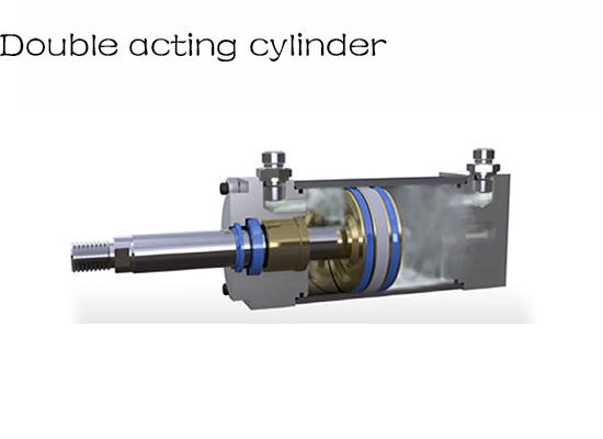
A double-acting cylinder uses compressed air for both extension and retraction. It normally has a port for each side of the piston and is controlled by a directional valve. This gives the machine active pneumatic control in both directions and makes the design suitable for a wide range of industrial pushing, pulling, clamping, lifting and positioning tasks.
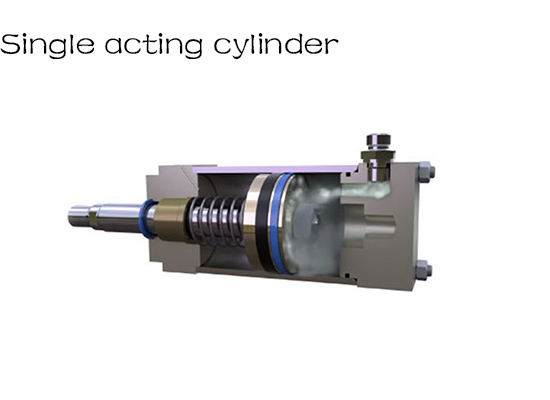
A single-acting cylinder uses compressed air to drive the piston in one direction. Return motion is produced by a spring or, in some designs, by an external load. Because the return mechanism occupies space and has its own force characteristics, single-acting cylinders are usually selected for applications where this simpler one-direction pneumatic action fits the machine requirement.
Neither principle is universally better. The correct choice depends on the required motion, force in each direction, available space, fail-state behavior, cycle requirements and control strategy.
The cylinder generates force internally, but the cylinder body must react that force back into the machine. This is why mounting is part of how the actuator works in a real mechanism, even though the mounting itself does not generate power.
Common arrangements include foot, flange, clevis and trunnion mounting. The correct choice depends on whether the cylinder should remain fixed, pivot as the mechanism moves, or fit within a particular installation envelope.
A good mounting arrangement keeps the piston rod aligned with the intended load path. If the mechanism forces the rod sideways, side load can increase friction and wear on the rod seal, bearing surfaces and guides. Where the load cannot be kept in line with the cylinder, an external guide or a different actuator arrangement may be required.
As the piston approaches the end cover, the moving mass still has kinetic energy. At low speed and low load, a simple elastic bumper may be sufficient. At higher speeds or with larger moving masses, the cylinder may use pneumatic cushioning or the machine may require an external shock absorber.
This is an important part of cylinder operation because producing enough force to move a load does not automatically mean the cylinder can stop that load smoothly. Repeated hard impact at the end of stroke can increase noise and shorten component life.
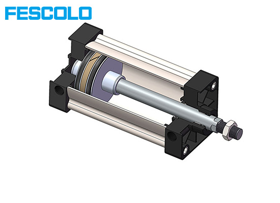
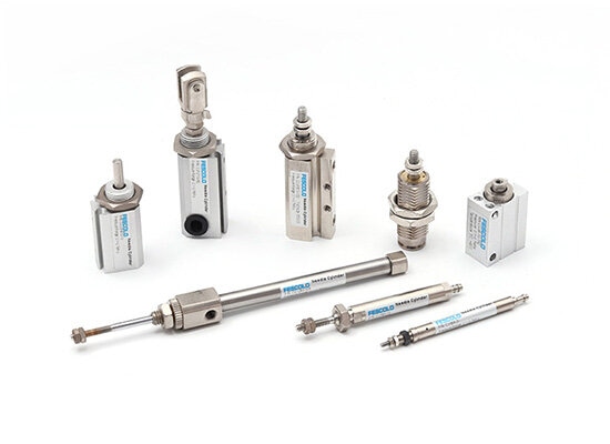
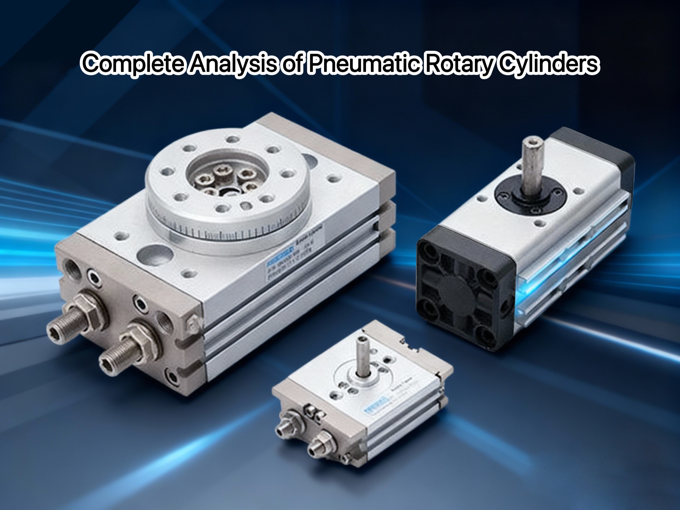
Most pneumatic cylinders use the same basic idea: compressed air creates a pressure difference that produces mechanical motion. The way that motion is transferred to the machine, however, can be quite different.
Cylinder design | How motion is produced or transferred | Why the design is used |
Single-rod cylinder | An internal piston drives one external piston rod. | General-purpose industrial linear motion. |
Double-rod cylinder | The piston rod extends from both ends of the piston. | Useful where more symmetrical rod-side behavior or motion from both ends is needed. |
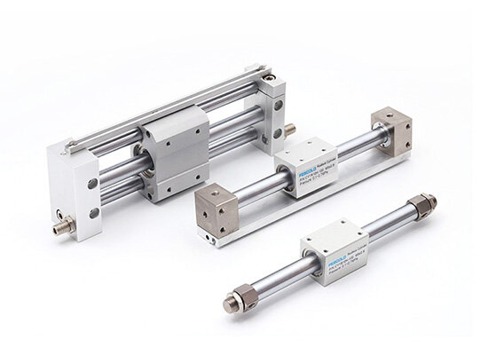
An internal piston transfers motion to an external carriage through a mechanical or magnetic coupling. | Long travel where avoiding a projecting piston rod can reduce installation length. | |
Special-purpose cylinders | The pneumatic principle is combined with application-specific mechanisms or structures. | Functions such as stopping, clamping, guided motion, compact layouts or multiple positions. |
The important point is that “pneumatic cylinder” describes a family of actuators, not one single mechanical layout. Understanding the load path and motion requirement is often more useful than choosing a cylinder only by its outside appearance.
Pneumatic and hydraulic cylinders can look similar because both use pressure acting on a piston to create mechanical motion. Their working media and system behavior are different, so one should not be treated as a direct substitute for the other without checking the application.
Pneumatic cylinder | Hydraulic cylinder | |
Working medium | Compressed air | Hydraulic fluid |
Medium behavior | Compressible | Nearly incompressible |
Typical strengths | Clean point-of-use actuation, fast repetitive motion, relatively simple pneumatic circuits | High force density and strong load-control capability |
System consideration | Air supply, treatment, valves, exhaust and flow capacity | Pump, reservoir, valves, return circuit and fluid management |
In some industrial equipment, designers evaluate pneumatic actuation as an alternative when the required force can be achieved with compressed air and avoiding hydraulic oil at the point of use is an important design consideration. The change is not simply a matter of replacing a hydraulic cylinder with a pneumatic cylinder of similar dimensions.
Force, available air pressure, stroke, speed, mounting, load behavior, control requirements and the safe behavior of the machine if air pressure is lost all need to be reviewed. For that reason, changing the actuation method is an engineering evaluation rather than a one-for-one component substitution.
Once the basic motion is understood, reliable cylinder operation depends on how well the actuator matches the machine. In practice, the following questions are more useful than simply asking whether a cylinder can extend and retract:
• Is enough force available at the lowest realistic operating pressure?
• Does the stroke match the required travel without creating unnecessary overhang?
• Can the valve and air lines provide enough flow for the required speed?
• Is the load aligned with the piston rod, or does it need external guidance?
• Is the mounting arrangement suitable for the motion of the mechanism?
• Does the moving mass need adjustable cushioning or an external shock absorber?
• Are the environment, temperature, contamination and duty cycle compatible with the cylinder design?
This is also why custom cylinder development normally begins with application data rather than only a requested bore and stroke. A useful cylinder specification describes what the machine needs the actuator to do and the conditions under which it must do it.
Compressed air is directed into a cylinder chamber. Pressure acting on the effective piston area creates force, and the piston moves when that force exceeds the opposing load and resistance. The opposite chamber must also be able to exhaust.
A directional control valve routes compressed air to the required cylinder port and connects the opposite side to exhaust. Switching the valve reverses the pressure difference and therefore reverses cylinder motion.
Stroke is the designed travel distance of the piston between its end positions. It determines how far the mechanism can move, while bore and pressure are more directly related to available force.
Higher pressure can increase the available force, but cylinder speed also depends strongly on airflow, valve and port capacity, tubing, flow controls, load and exhaust conditions. Pressure and flow should not be treated as the same parameter.
The two ports allow compressed air to be applied alternately to either side of the piston. One chamber is pressurized while the other exhausts, allowing active pneumatic motion in both directions.
Sometimes, but not as a direct one-for-one substitution. The required force, available pressure, stroke, speed, mounting, control behavior and machine safety requirements must be evaluated before changing the actuation method.
The engineering principles in this article follow standard pneumatic actuator practice. For additional technical reference, consult the current documentation for the cylinder and valve series used in the machine, together with applicable ISO or manufacturer specifications for dimensions, pressure ratings, mounting and application limits.

Whatsapp QR:

WeChat QR:

Tell us about your application requirements. Our engineers will review your project and provide practical feedback within 1–2 working days.

Fescolo is the specialized custom pneumatic cylinder brand operated by Ningbo Fokca Automation Co., Ltd.
Looking for standard pneumatic and automation components?
Visit Fokca
© 2026 Ningbo Fokca Automation Co., Ltd. All Rights Reserved. Sitemap