Mar 10, 2025
At 2800 mm, stroke stops being just a dimension. It starts changing the rest of the design.
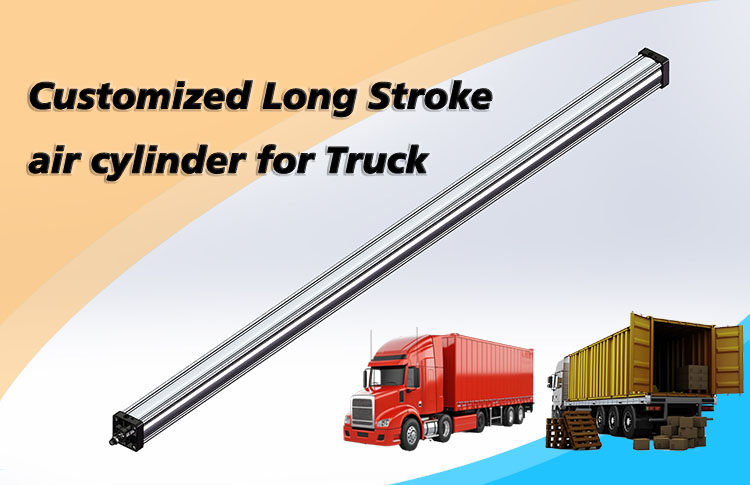
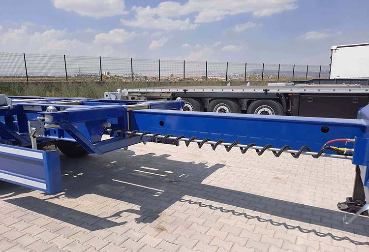
That is what makes this truck project useful beyond the project itself. A customer needed a pneumatic cylinder to drive a movable rear support on a heavy-duty truck. The cylinder was mounted horizontally beneath the rear frame, used a 100 mm bore, and required a maximum stroke of 2800 mm. The original project also specified a stainless-steel piston rod for the outdoor vehicle environment.
The obvious feature is the long travel. The more useful question is what that travel changes around the cylinder: rod stability, guidance, alignment, airflow, stopping behavior and the way the actuator fits the machine. A long-stroke pneumatic cylinder is not simply a standard cylinder with a longer tube and rod.
Using this 2800 mm truck project as a starting point, we can see the same issues that appear in many long-stroke, special-size and retrofit cylinder applications.
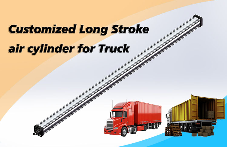
The truck uses an extendable rear support or sliding structure so the vehicle can adapt to different cargo arrangements. The pneumatic cylinder sits under the rear frame and provides the linear push-pull motion that extends or retracts that support.
Project item | Confirmed case detail | Engineering significance |
Application | Heavy-duty truck rear support | The actuator works inside a mobile, outdoor mechanical system rather than a clean fixed machine. |
Stroke | Maximum 2800 mm | Multi-meter travel brings rod stability, alignment, airflow and motion-control questions to the foreground. |
Bore | 100 mm | Bore relates to force; stroke relates to travel. They solve different parts of the application. |
Installation | Horizontal under rear frame | Guidance and side-load control become especially important over long travel. |
Piston rod | Stainless steel | The project required improved corrosion resistance for an outdoor vehicle environment. |
There is no universal point at which a cylinder suddenly becomes “long stroke.” What matters is when the travel begins to change the mechanical and pneumatic behavior of the application. That depends on the cylinder architecture, rod size, mounting, load, speed, guidance and environment.
With a conventional rod-type cylinder, multi-meter travel is enough to bring several of those issues to the front. The question changes from “What stroke do I need?” to “What happens to the machine when the actuator has to travel that far?”
As stroke increases, three things quickly become more important: the cylinder has more air to fill and exhaust, the extended rod becomes more sensitive to bending and instability, and higher speed makes the end of the stroke harder to stop smoothly. In practice, the cylinder has to be considered together with the load, guides, air circuit and machine structure.
When a cylinder pushes, the extended piston rod is working under compression. With a short stroke, this may cause little concern. As the rod reaches farther out, however, it becomes more sensitive to bending and instability. That makes rod diameter, mounting arrangement and external guidance much more important in a long-stroke application.
The change is not gradual. As the unsupported rod becomes longer, its resistance to buckling can fall quickly. A larger rod diameter can improve stiffness significantly, but the right choice still depends on how the cylinder is mounted and how the load acts on it.
Engineering shortcut: a longer unsupported rod can lose stability surprisingly quickly. Rod diameter, mounting and guidance therefore deserve early attention - not a final check after the cylinder has already been sized.
So a rod that works well at a moderate stroke may not be suitable when the travel becomes much longer. Theoretical push force is only part of the decision; the rod also has to remain stable while delivering it.
For a 2800 mm pushing application like this one, rod stability deserves a dedicated check rather than being treated as an afterthought.
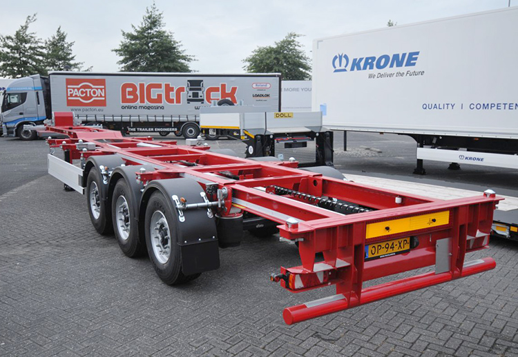
A pneumatic cylinder is designed to push and pull along its axis. It should not automatically be expected to guide a heavy sliding structure at the same time. If the moving support, platform or fixture hangs on the piston rod, the rod bearing and seals can be forced to carry side load and bending that they were not intended to handle.
The longer the travel, the less forgiving the mechanism becomes. A small alignment error can become more troublesome farther along the stroke, and on mobile equipment, chassis movement or structural deflection can add to the problem.
A better arrangement is usually to let rails, slides or bearings guide the load while the cylinder supplies the linear force. Where appropriate, a suitable joint or floating connection can also keep small alignment errors from being transferred directly into the rod.
A practical question to ask during design: when the cylinder is fully extended, what is actually guiding the load? If the answer is mainly 'the piston rod,' the mechanism is worth reviewing.
The two headline dimensions in this truck project do very different jobs. The 2800 mm stroke tells us how far the support must travel. The 100 mm bore determines piston area and therefore strongly influences how much pneumatic force is available at a given pressure.
This prevents a common mistake: treating a special cylinder as if it had one overall 'size.' Bore, stroke, rod diameter, mounting, guidance and speed each solve a different part of the application.
Making the stroke longer does not give the cylinder more force. It gives the mechanism more travel - and at the same time creates new questions about rod stability, air volume, alignment and stopping behavior.
A long-stroke cylinder can be mechanically correct and still disappoint in operation if the air system cannot keep up.
With the confirmed dimensions from this case, a 100 mm bore and 2800 mm stroke create about 22 liters of geometric cap-end volume. That number is useful because it shows the scale of the air that must enter and leave the cylinder during each full movement. Actual compressed-air consumption will still depend on working pressure, return-side volume and the operating cycle.
For the machine builder, the practical issue is response. If the valve, tubing or flow controls are too restrictive, a cylinder that looks correct on a force calculation may still move more slowly than expected. Long-stroke selection therefore includes the air path, not only the actuator.
Think of the motion as one system: cylinder + valve + tubing + flow controls + supply pressure + moving load + required cycle time.
Increasing speed can make a long-travel mechanism much more productive, but it also makes the end of the stroke more demanding. The faster the moving assembly arrives, the more energy has to be managed when it stops.
The increase is not one-for-one: if the moving mass stays the same and speed doubles, kinetic energy becomes four times greater. A modest speed increase can therefore change the cushioning requirement significantly. Depending on the application, adjustable air cushioning, an external shock absorber or controlled deceleration may be needed.
A long stroke does not automatically require an external shock absorber. The choice depends on moving mass, actual speed, cycle frequency and mechanism geometry. What matters is checking the stopping condition instead of assuming standard cushioning will be enough.
The original project used a stainless-steel piston rod. On vehicle-mounted equipment, that detail can matter because the exposed rod may see moisture, road dirt, dust and changing weather that an indoor automation cylinder never encounters.
But 'outdoor use' is not a complete specification. Road salt, washdown chemicals, abrasive dust, low-temperature starts and direct water spray can each change what is appropriate for the rod surface, wiper, seals and external finish.
The same applies to seals: temperature matters, but so do pressure, lubrication, contamination and cycling. The operating environment should be described as a whole rather than reduced to one temperature number.
Custom cylinders are often associated with very large bores or very long strokes. In real equipment, some of the most valuable changes are smaller: a different mounting center, shorter retracted length, special rod end, better port direction, easier sensor position or a material change for the environment.
What is unusual? | Typical custom change | Why it can matter |
Travel distance | Exact non-standard stroke | Matches the real motion instead of forcing the machine to accept the next catalog stroke. |
Rod stability | Larger rod or different rod arrangement | Helps manage compression, buckling risk or stiffness on long travel. |
Mounting geometry | Custom pin centers, flange, clevis, trunnion or rod end | Lets a cylinder fit an existing frame or moving linkage. |
Installation space | Shorter body, different architecture or rodless layout | Useful when required travel is long but retracted space is limited. |
Ports and piping | Different port size, thread or orientation | Can simplify routing and reduce awkward hose/tube bends. |
Environment | Rod material, scraper/wiper, seals, coating or stainless components | Adapts the actuator to moisture, dust, corrosion, washdown or temperature conditions. |
Control | Magnetic piston, sensor provisions, cushioning or stroke adjustment | Makes the actuator easier to integrate into machine control and motion sequencing. |
That is a more useful way to think about customization: not making a cylinder 'non-standard' for its own sake, but making the actuator fit the machine with fewer compromises.
This is especially clear in retrofit work. An older machine may use an obsolete actuator, unusual mounting centers, a discontinued stroke, a special rod end or an installation space that leaves little room for a catalog cylinder.
Trying to force a standard cylinder into that space can create new brackets, linkages, adapters or piping changes. In some cases, designing the replacement cylinder around the existing machine is the simpler solution. The value of customization is then not a more complicated cylinder - it is a less complicated machine modification.
A replacement can also improve something that was always inconvenient: corrosion resistance, guidance, port position, cushioning or sensor integration.
The caution is not to copy the old cylinder blindly. If side load, poor guidance, inadequate cushioning or environmental exposure caused the old problem, reproducing every detail may reproduce the same failure. Keep the interfaces that matter; question the ones that caused trouble.
• Retracted and extended mounting-center distances, not just the cylinder body length.
• Required working stroke and any adjustment or overtravel that the mechanism actually needs.
• Bore, piston-rod diameter, rod-end thread and rear/front mounting style.
• Available operating pressure and the real push/pull load, including unfavorable load positions.
• Port size, thread type, port direction and available space for fittings and tubing.
• How the load is guided and whether the cylinder sees any side load or bending moment.
• Target speed, moving mass and how the machine stops at each end of travel.
• Sensors, magnetic piston requirements and control-system interface.
• Temperature, moisture, dust, chemicals, washdown or corrosion exposure.
• Photos of the complete mechanism at both ends of travel, plus the cylinder label and mounting details.
When a machine needs several meters of travel, ask one question before refining the dimensions: is a conventional rod-type cylinder still the best architecture? Sometimes it is; sometimes the available space or load arrangement points elsewhere.
Architecture | Often useful when | Key question to check |
Conventional rod cylinder | Simple axial push/pull, external mechanism already provides good guidance | Is the rod stable in compression, and is there enough retracted/extended installation length? |
Rodless cylinder | Long travel is needed but overall installation length is constrained | Can the slider, guide and moment/load ratings handle the real moving load? |
Cylinder + external linear guide | The load creates side force or moment that should not pass through the rod | Is the cylinder connected so the guide defines motion without creating binding? |
Hydraulic or electric actuator | Force, stiffness, precise positioning, energy use or control requirements exceed what the pneumatic arrangement does well | Does the application requirement justify a different actuator technology rather than stretching a pneumatic design beyond its strengths? |
A rodless cylinder, for example, can provide long travel without the extra installation length required by an extending piston rod. It is not automatically better - load moments, guidance, speed, sealing, environment and cost still matter. The point is to solve the machine's travel problem, not simply to make the longest possible rod.
For an OEM engineer, equipment builder or technical buyer, the most useful starting point is usually the machine, not a familiar cylinder part number. Define the movement first, then work back toward the actuator. That also makes it easier to decide whether a rod-type pneumatic cylinder is the right architecture in the first place.
Step | What to establish |
1. Define the motion | Required stroke, direction, available retracted/extended envelope and whether intermediate positions matter. |
2. Define the load | Push/pull force, moving mass, load direction, worst-case geometry and operating pressure. |
3. Define the guidance | What carries side load and moment? How is the moving member supported through the full travel? |
4. Check rod stability | For long push strokes, verify piston-rod diameter, effective buckling length, mounting condition and compressive force. |
5. Check the pneumatic circuit | Valve, tubing, fittings, flow control and exhaust capacity must support the desired speed. |
6. Check stopping behavior | Review moving mass, velocity, cushioning, external stops and any shock absorber or controlled deceleration requirement. |
7. Check the environment | Temperature, moisture, corrosion, dust, washdown, chemicals, lubrication and maintenance access. |
8. Then define the custom details | Exact stroke, rod end, mounting, ports, materials, sensors and other interfaces around the actual machine. |
A long-stroke pneumatic cylinder can be a practical choice when compressed air is available, the force requirement is reasonable, the motion is mainly between two end positions and the load has proper mechanical guidance.
Another actuator may make more sense when the application needs very high continuous force, high stiffness, precise multi-position control or large side-load capacity. That comparison is best made before the machine is designed around the wrong actuator concept.
Customization creates the most value when it removes a real application constraint, not when it is used to force one actuator technology into every job.
The same thinking applies far beyond this truck: extendable vehicle mechanisms, sliding platforms, transfer equipment, large doors and hatches, test equipment, long-travel mechanisms and older machines that need a hard-to-find replacement actuator.
In a retrofit, the right special-size cylinder can preserve useful machine geometry and reduce reconstruction. In a new design, it can give the engineer more freedom to place the actuator where the mechanism needs it. In both cases, the cylinder should fit the machine - not the other way around.
Yes, especially for a conventional rod-type cylinder. There is no universal millimeter threshold for “long stroke,” but multi-meter travel requires more attention to rod stability, alignment, guidance, air volume, installation length and end-of-stroke behavior than a typical short-stroke catalog application.
Not automatically. Bore and stroke solve different requirements. A longer stroke can change piston-rod buckling, side-load sensitivity, total installation envelope, air volume and stopping behavior even when the force requirement is unchanged.
A rodless cylinder can be attractive when long travel is required but the available installation length is limited. Selection still needs to consider load mass, moment, guide capacity, speed, cushioning and environmental conditions. Rodless is an alternative architecture, not a universal replacement for a rod-type cylinder.
Start with retracted and extended mounting-center dimensions, stroke, bore, piston-rod diameter, mount types, port details, pressure, load direction, speed, environment, sensors and clear photos or drawings of the complete mechanism. For a long-stroke application, also explain how the load is guided.
Yes, when the change addresses a real application problem. A replacement project can be an opportunity to correct an inconvenient port location, add sensing, improve corrosion resistance, revise cushioning, change mounting or solve a recurring alignment issue. The original machine dimensions should be respected where necessary, but old design weaknesses do not need to be copied blindly.
The interesting part of this 2800 mm truck cylinder is not the number itself. It is what that distance changes around the actuator.
Longer travel makes rod stability, airflow, stopping behavior, guidance and alignment harder to ignore. On mobile equipment, the environment adds another layer of decisions around materials and protection.
A useful custom-cylinder discussion therefore starts with the equipment: what has to move, how far, how fast, under what load, along what guide, in what environment and inside what available space. Those answers usually tell us more than a catalog part number.
For a new, replacement or retrofit long-stroke cylinder, a machine drawing or installation sketch plus the operating conditions is usually the best starting point. The goal is not merely to reproduce a dimension, but to make the actuator work naturally with the machine around it.

Whatsapp QR:

WeChat QR:

Tell us about your application requirements. Our engineers will review your project and provide practical feedback within 1–2 working days.

Fescolo is the specialized custom pneumatic cylinder brand operated by Ningbo Fokca Automation Co., Ltd.
Looking for standard pneumatic and automation components?
Visit Fokca
© 2026 Ningbo Fokca Automation Co., Ltd. All Rights Reserved. Sitemap