Apr 23, 2025
A pneumatic cylinder looks simple from the outside: a barrel, two ends and a rod that moves in and out. Inside, however, several components have to work together with the correct clearances, sealing, guidance and alignment. A problem in one part can quickly appear as air leakage, unstable motion, loss of force or premature wear somewhere else.
Understanding the main pneumatic cylinder parts is useful not only for maintenance. It also helps engineers and buyers compare cylinder designs, identify the likely cause of a failure, and communicate more clearly when a standard cylinder needs to be modified for a machine.
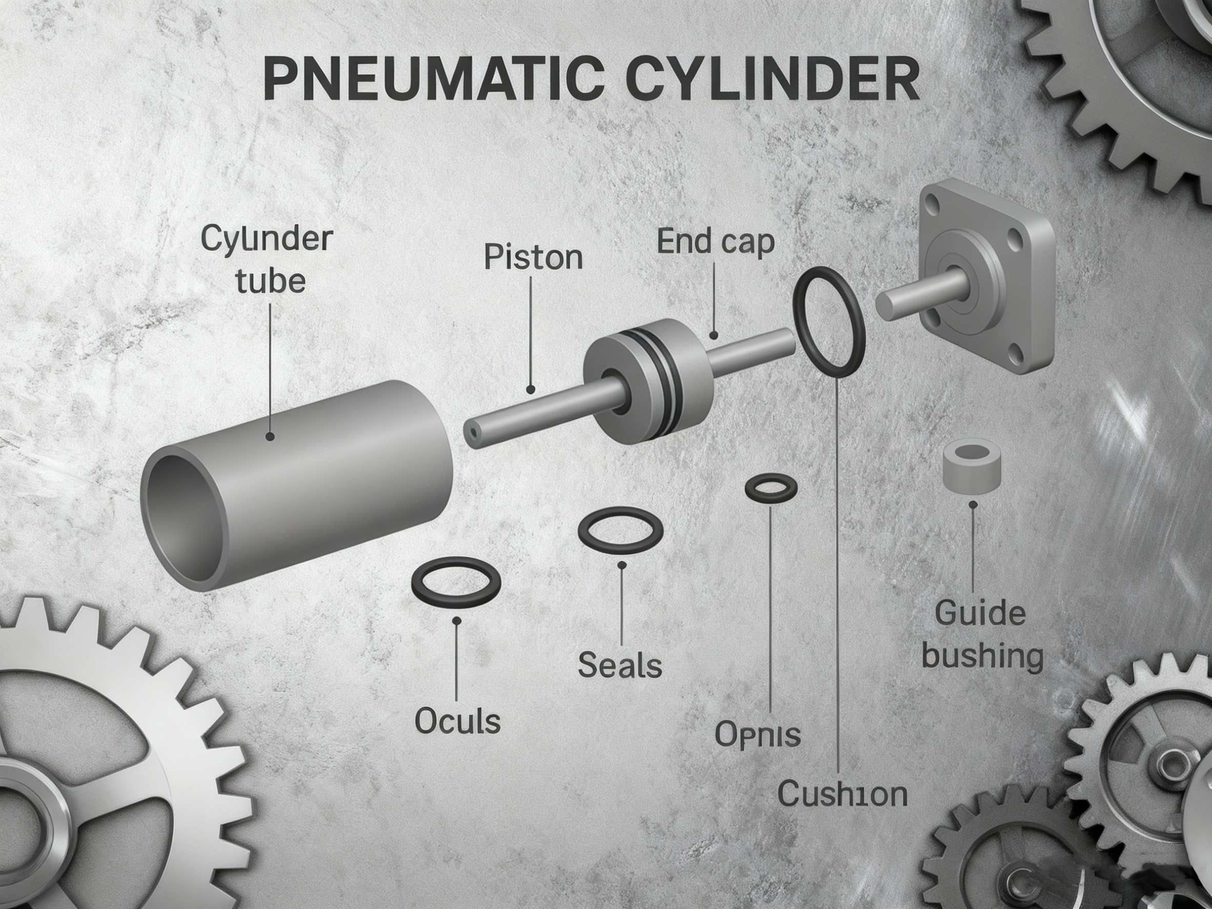
A typical single-rod pneumatic cylinder contains a cylinder barrel, piston, piston rod, front and rear end caps, seals, guide or bearing elements, air ports and fastening components. Depending on the design, it may also include adjustable cushioning, a magnetic piston for position sensing, wear rings, tie rods, mounting threads or external mounting accessories.
Part | Main function | What it affects |
Cylinder barrel / tube | Forms the pressure chamber and guides the piston | Sealing, friction, alignment, service life |
Piston | Separates the two pressure chambers and transfers air pressure into force | Force generation and motion |
Piston rod | Transfers piston force to the external load | Load capacity, alignment, buckling resistance |
End caps | Close the cylinder and carry ports, guides and seals | Air distribution, support and mounting |
Seals | Limit internal and external air leakage | Efficiency, friction and service life |
Rod guide / bearing | Supports and guides the piston rod | Side-load resistance and rod alignment |
Cushioning components | Decelerate the piston near end of stroke | Impact, noise and end-of-stroke life |
Magnet and sensor interface | Allows non-contact piston position detection when equipped | Machine sequencing and feedback |
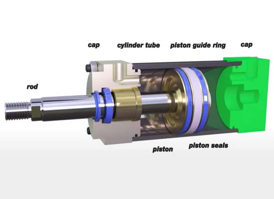
The cylinder barrel forms the working chamber in which the piston travels. Its internal surface directly interacts with the piston sealing system, so bore geometry, surface finish, straightness and cleanliness can affect friction, leakage and seal life.
Aluminum alloy is common in industrial pneumatic cylinders because it provides a useful balance of weight, manufacturability and corrosion resistance. Other materials may be selected when the environment, cleaning process, temperature or mechanical requirements are different. The important point is that barrel material and surface treatment should match the application rather than being treated as a cosmetic specification.
The piston divides the barrel into pressure chambers. When compressed air creates a pressure difference across the piston, the resulting force moves the piston and the connected rod. The effective piston area is therefore one of the main factors that determines theoretical cylinder force.
In a single-rod double-acting cylinder, the rod occupies part of the piston area on the retraction side. This is why retraction force is normally lower than extension force at the same pressure. For the calculation itself, see the related guide Pneumatic Air Cylinder Force Calculation.
The piston rod carries the internal piston motion to the external mechanism. It must withstand axial load while maintaining a surface suitable for the rod seal and guide. Rod diameter, material, surface condition, unsupported length and load direction all matter.
A common mistake is to evaluate a rod only by tensile or compressive force. On long strokes, a slender rod under compression can become limited by buckling before the cylinder reaches its theoretical force capability. Side load is another concern: a pneumatic cylinder is primarily intended to produce axial motion, not to act as the main linear guide for a poorly aligned mechanism.
Pneumatic cylinders normally use several sealing functions rather than one universal seal. Piston seals limit leakage between chambers, rod seals limit leakage to atmosphere, and static seals close joints between fixed components. A wiper or scraper may also help reduce the amount of contamination carried inward by the moving rod.
Seal material and profile influence leakage, breakaway friction, running friction, temperature capability and wear. A harder or more aggressive seal is not automatically better. The sealing system has to match pressure, speed, lubrication condition, temperature, contamination and the cylinder geometry.
The rod guide or bearing supports the piston rod as it passes through the front end cap. Its job is to maintain alignment and control radial movement while allowing low-friction axial travel. Excessive side load can accelerate wear of the guide, rod seal and rod surface at the same time.
If a machine load requires substantial guidance, an external linear guide or a guided-cylinder design is often more appropriate than expecting a conventional cylinder rod to absorb the moment load by itself.
The end caps close the pressure chamber and integrate several functions. Depending on the cylinder design, they may contain the air ports, rod guide, rod seal, cushion needle, cushion seal, mounting threads or structural fasteners. Their geometry also helps maintain the alignment of the barrel and internal components.
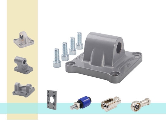
This is one reason apparently similar cylinders are not always interchangeable. Port position, mounting interface, overall length, rod thread and end-cap geometry can matter as much as bore and stroke when the cylinder must fit an existing machine.
At higher speeds or with heavier moving loads, allowing the piston to strike the end cap directly can create noise, vibration and repeated impact stress. Pneumatic cushioning reduces piston speed near the end of stroke by restricting the exhaust air during the final portion of travel.
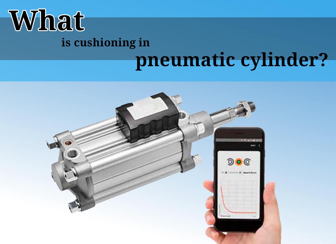
Some cylinders use fixed cushioning, while others provide adjustable pneumatic cushioning. The correct setting depends on moving mass, speed, pressure and cycle conditions. Cushioning is not a substitute for correct cylinder sizing or external shock absorption when the application energy is too high. See What Is Pneumatic Cylinder Cushioning? for a more detailed explanation.
Many industrial cylinders include a permanent magnet in the piston so an externally mounted reed switch or electronic cylinder sensor can detect when the piston enters its sensing zone. This allows the control system to confirm an end position or another selected point without mechanical contact with the piston.
The magnet does not make the cylinder move and it does not, by itself, provide continuous precision position control. Its purpose is to make piston position detectable by a compatible external sensor. Sensor type, mounting position and switching characteristics should therefore be selected as part of the control system.
The air ports connect the cylinder chambers to the directional control valve. Port size is only one part of the flow path: valve capacity, tubing size, fittings, silencers and restrictions can all influence how quickly air enters and leaves the cylinder.
This is why two cylinders with the same bore and stroke can behave differently when installed in different pneumatic circuits. Force depends strongly on the pressure available at the piston, while operating speed is also influenced by how quickly the chambers can fill and exhaust.
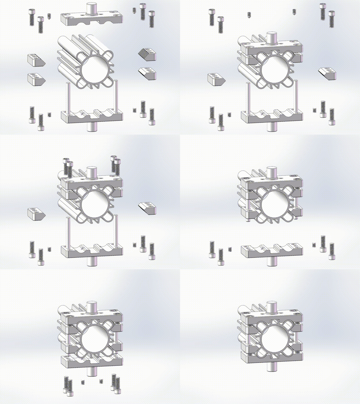
Different cylinder families hold the barrel and end caps together in different ways. Tie-rod cylinders use external rods, while other designs may use threaded, crimped, bolted or profiled-barrel constructions. The construction affects serviceability, overall dimensions and how loads are carried through the cylinder body.
This matters during maintenance: a cylinder should not be disassembled simply because another cylinder with a similar appearance can be rebuilt. The manufacturer's service instructions and the actual construction should be checked first. For a maintenance-focused procedure, see How to Safely Disassemble a Pneumatic Cylinder for Maintenance and Inspection.
When the directional valve supplies compressed air to one cylinder chamber, pressure acts on the piston area. The piston moves, the piston rod transfers that motion to the machine, and air from the opposite chamber is exhausted. Throughout the stroke, seals maintain the pressure separation, the barrel guides the piston, and the rod guide supports the rod. Near the end of travel, cushioning may reduce impact before the piston reaches its end position.
The useful engineering lesson is that cylinder performance is a system result. Increasing bore changes force and air consumption; changing rod diameter affects retraction area and stability; changing seals can affect friction; changing stroke can alter rod stability; and changing mounting can change the loads seen by the rod and guide.
There is no single “most important” component. The correct design depends on what the machine asks the cylinder to do. For a custom cylinder project, the useful starting information normally includes required force, available working pressure, bore or installation envelope, stroke, load direction, speed and cycle rate, mounting, rod connection, environment and any sensing or cushioning requirements.
At Fescolo, these application conditions are considered together before changing individual dimensions or materials. A larger rod, different seal, special mounting or non-standard stroke only makes sense when it solves a defined requirement without creating a new limitation elsewhere in the cylinder.
Symptom | Possible areas to inspect |
External air leakage near the rod | Rod seal, rod surface, guide wear, alignment |
Cylinder drifts or loses force | Piston seal, internal leakage, valve/circuit, available pressure |
Jerky or high-friction motion | Seals, lubrication condition, contamination, alignment, side load |
Rod or guide wears unevenly | Side load, mounting alignment, guide/bearing, rod straightness |
Hard impact at end of stroke | Speed, moving mass, cushioning adjustment, external shock control |
Sensor does not switch reliably | Magnet/sensor compatibility, sensor position, wiring, switching distance |
The main parts are typically the barrel, piston, piston rod, front and rear end caps, seals, rod guide or bearing, air ports and structural fasteners. Many cylinders also include cushioning and a magnetic piston for position sensing.
Compressed air pressure acting on the effective piston area creates the theoretical force. The piston transfers this force to the piston rod, which delivers it to the external mechanism.
Seal wear can result from normal cycling, contamination, poor surface condition, unsuitable material, excessive temperature, lack of appropriate lubrication, misalignment or side load. Replacing a seal without finding the cause can lead to repeated failure.
Not always. For primarily axial loads, the cylinder's internal rod guide may be sufficient. Loads with significant side force or moment often require an external guide or a guided-cylinder design.
A piston magnet allows a compatible external sensor to detect piston position without direct mechanical contact. It is used for machine feedback and sequencing, not to generate cylinder force.

Whatsapp QR:

WeChat QR:

Tell us about your application requirements. Our engineers will review your project and provide practical feedback within 1–2 working days.

Fescolo is the specialized custom pneumatic cylinder brand operated by Ningbo Fokca Automation Co., Ltd.
Looking for standard pneumatic and automation components?
Visit Fokca
© 2026 Ningbo Fokca Automation Co., Ltd. All Rights Reserved. Sitemap